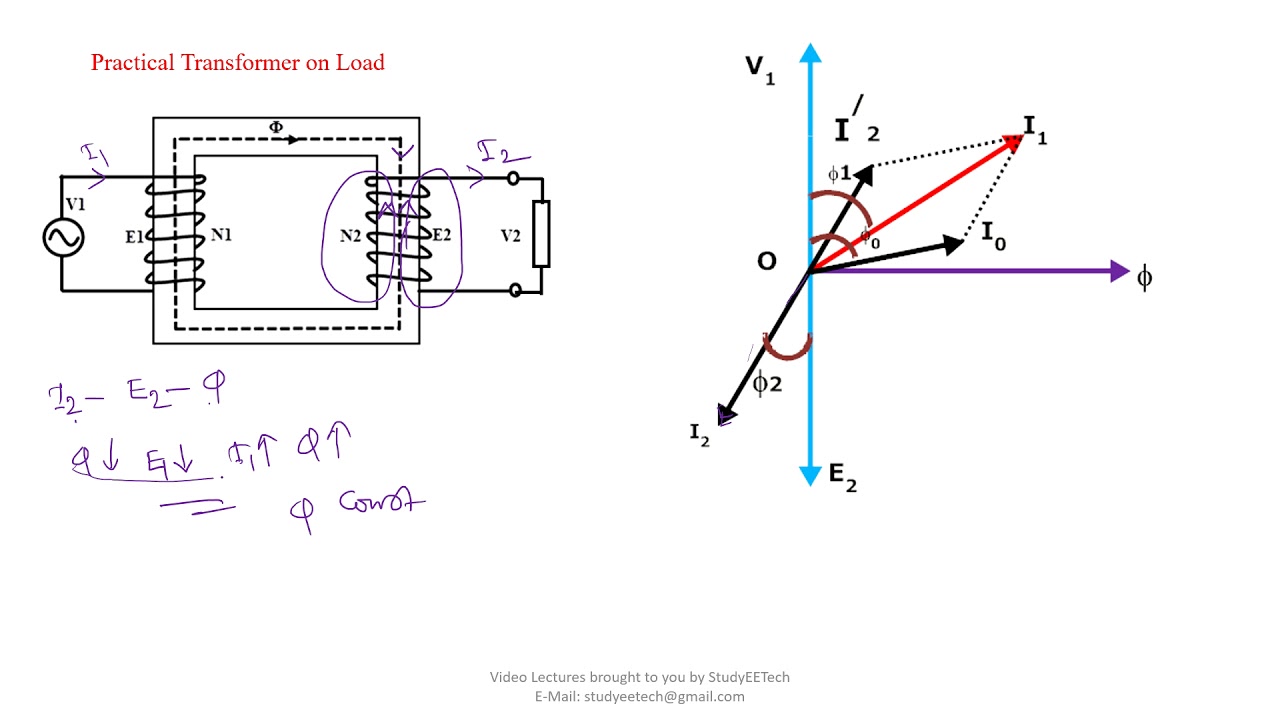
Phasor diagrams for transformer on load Transformer on no load condition Phasor draw diagram
Phasor Diagrams for Transformer on Load | your electrical home
Phasor unbalance Transformer phasor Phasor diagram load generator transformer power factor unity motor diagrams wiring induction electrical circuit synchronous electricity capacitor fig
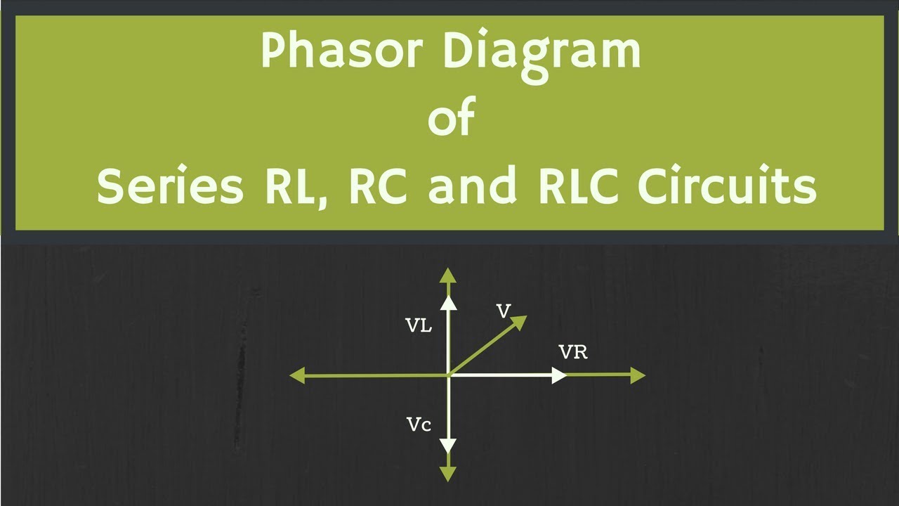
Phasor diagram of rlc circuit
Phasor diagram, how to drawElectrical power explained – part 3: balanced three-phase ac power 12+ phasor diagram of rlc series circuitHow to draw a phasor diagram ?.
3 phase transformer diagramTransformer phasor loading current diagram load phase diagrams primary calculate gif methods currents given io following (pdf) transformer working principle of transformer · 2020-03-281: phasor diagram of the unbalance load.
Phasor diagram of capacitor
Phasor diagram, how to draw a phasor diagram...What are phasors Diagram of complete ac circuitPhasor diagram of rl parallel circuit.
Balanced phasor electrical explained fluke waveforms samePhasor diagram draw online Draw a phasor diagram to represent the current and supply voltage appropr..40 phasor diagram rlc circuit.

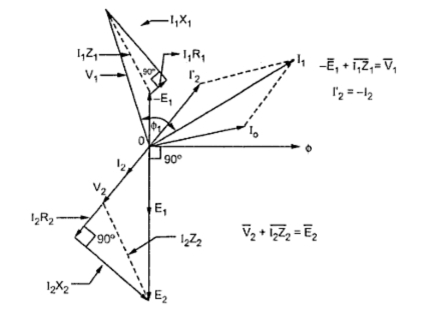
Transformer with resistance and leakage reactance
Phasor diagrams of ac circuitsPhase diagram ac circuit Phasor diagram 3 phase ac circuitHow to draw phasor diagram at how to draw.
Transformer loading and on-load phasor diagrams[diagram] single phase phasor diagram Rc circuit phasor diagramPhasor diagram draw.
Draw phasor diagram of single phase transformer on resistive load
Transformer wiring diagram explainedBasic phasor diagram electric circuit Transformer leakage reactance diagram phasor load resistance figure electricalPhasor diagram of capacitor.
Amazing how to draw a phasor diagram for transformer of the decade don .


Draw a phasor diagram to represent the current and supply voltage appropr..

PHASOR DIAGRAM, HOW TO DRAW - YouTube
Phasor Diagram Of Rl Parallel Circuit

1: Phasor diagram of the unbalance load | Download Scientific Diagram

What are Phasors - Definition, Examples & Diagram

Transformer Wiring Diagram Explained - Wiring Draw

Electrical Power Explained – Part 3: Balanced three-phase AC power | Fluke

phasor diagram of rlc circuit - Wiring Diagram and Schematics
